What is PV power generation?
A power generation technology that directly converts solar energy into electrical energy by utilizing the photovoltaic effect of semiconductor materials.
The photovoltaic effect—the phenomenon where light exposure creates a potential difference between different regions of a non-uniform semiconductor or a semiconductor-metal junction—serves as the physical basis for PV power generation.
Core system objective: To efficiently, safely, and stably convert solar radiant energy into alternating current (AC) electricity that meets grid requirements, and to transmit it to the grid.
Key application scenarios: Widely used in distributed rooftop power plants, large-scale ground-mounted power plants, Building-Integrated Photovoltaics (BIPV), and portable PV power supplies.
PV modules (solar panels) are the core of the system; their performance directly determines the efficiency and power output of the entire generation system.
Basic structural unit: Composed of multiple solar cells (individual units) connected in series and parallel, then encapsulated within glass, EVA, a backsheet, and an aluminum alloy frame to form the smallest independently functional power generation unit.
Main technical pathways: Mainstream panel technologies include monocrystalline silicon and polycrystalline silicon, as well as rapidly developing high-efficiency technologies such as thin-film cells, PERC, TOPCon, and HJT.
Since the power output of a single PV module is limited, multiple modules are typically connected in series and parallel to form a PV array, meeting specific system voltage and power requirements.
Series connection: Connecting the positive and negative terminals of multiple modules end-to-end to increase output voltage, thereby meeting the input voltage requirements of equipment such as inverters.
Parallel connection: Connecting multiple series-connected module strings in parallel to increase the system's total output current, thereby boosting the power output of the entire PV array.
The PV combiner box is located between the PV array and the inverter; it collects DC cables from multiple PV strings, facilitating centralized management and maintenance. Core function of the combiner box: To collect DC current from multiple PV module strings and output it to the inverter.
Safety and Monitoring
Overcurrent protection: Each circuit is equipped with a fuse; if a specific module string experiences a short circuit or anomaly, the fuse blows to protect the system without affecting other circuits.
Reverse polarity protection: Prevents equipment damage caused by reversed positive and negative connections.
Anti-reverse charging protection: Prevents the inverter or other branches from feeding current back into the modules.
Overvoltage protection: Limits overvoltage on the DC side.
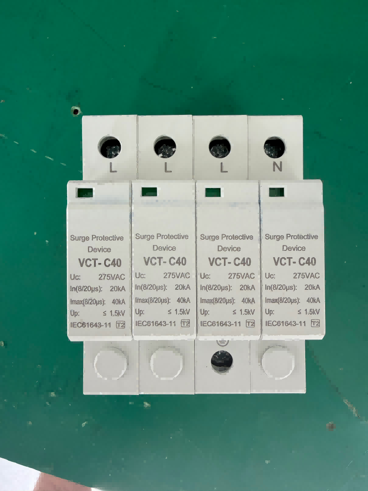
Built-in DC surge protective device (SPD): Diverts lightning current to the ground in the event of induced lightning or voltage surges.
Protects downstream equipment—such as inverters—from lightning damage.
Real-time monitoring of current, voltage, and temperature for each circuit.
Fault alarms: Automatically triggers an alarm if there is abnormal current in a circuit or if a fuse blows.
Communication interfaces (RS485/Ethernet): Enables remote monitoring, allowing O&M personnel to quickly locate faulty strings.
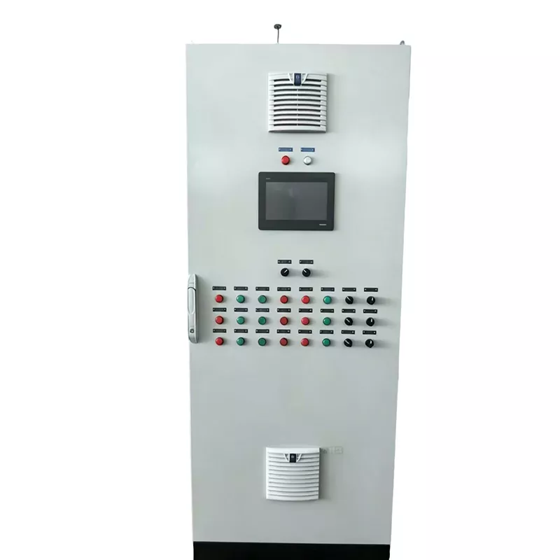
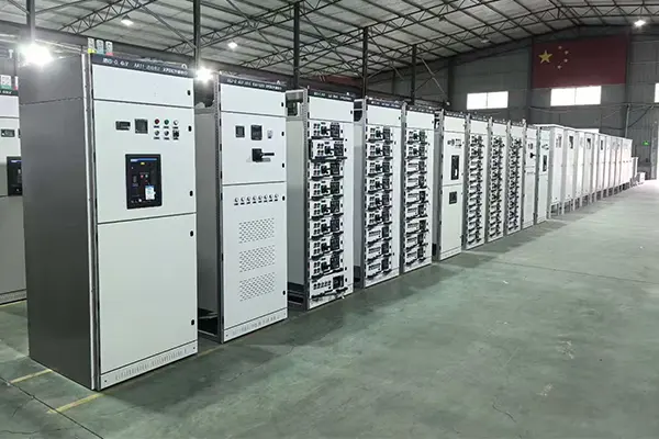
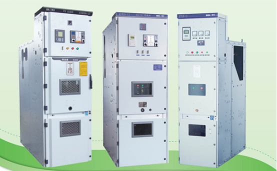
The DC distribution cabinet serves as the "hub" of the DC side, used to further aggregate and distribute electrical energy while providing a stable, safe input for the inverters.
Receives DC power from combiner boxes and distributes it to the corresponding inverter units based on system design and inverter configuration.
Equipped with various protection devices—such as DC circuit breakers and surge protective devices (SPDs)—to prevent system damage from overloads, short circuits, and lightning strikes.
PV Grid-Connection Cabinet
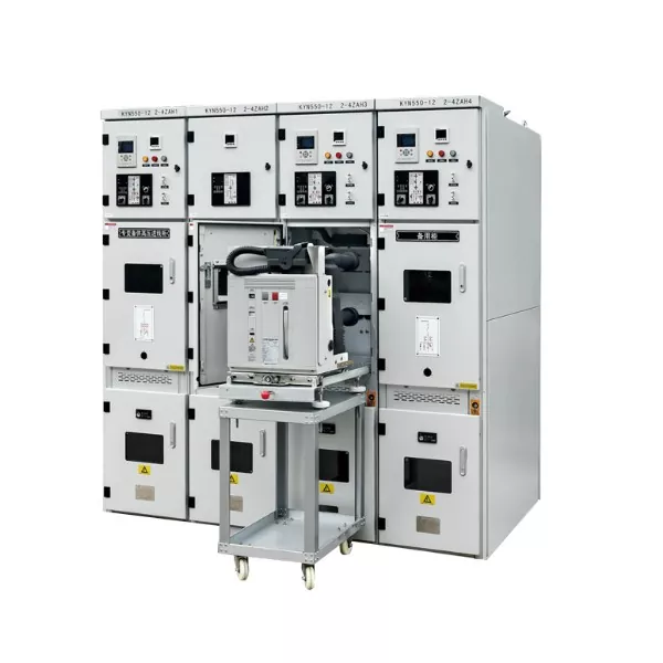
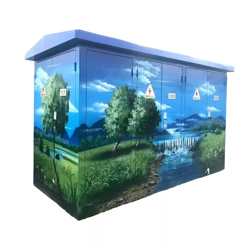
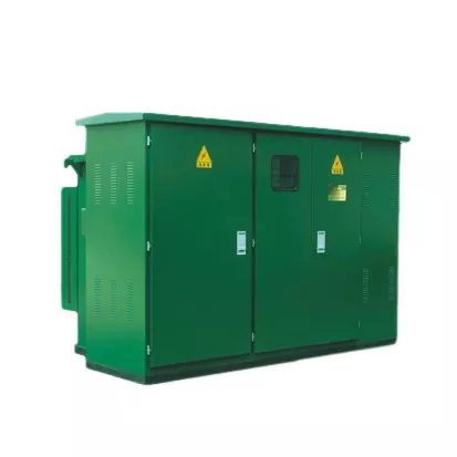
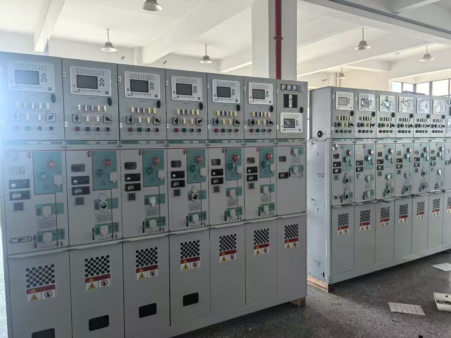
Also known as a PV grid-tie distribution cabinet or anti-islanding cabinet, this is specialized power distribution equipment in a PV system that connects the inverter output to the public grid.
It acts as the "interface master switch" between the PV power plant and the grid; all electricity generated by the PV system must pass through it to be fed into the grid. Core Functions
1. Aggregation Function
Collects AC outputs from multiple inverters into the grid-connection cabinet
Example: 10 x 100kW inverters → Aggregation in grid-connection cabinet → Single 1MW output
2. Grid-Connection Protection (Critical)
Over-voltage protection: Disconnects when grid voltage is too high
Under-voltage protection: Disconnects when grid voltage is too low
Over-frequency protection: Disconnects when grid frequency is too high
Under-frequency protection: Disconnects when grid frequency is too low
Anti-islanding protection: Automatically detects grid outages and disconnects to prevent the PV system from energizing the de-energized line (mandatory grid requirement)
3. Metering Function
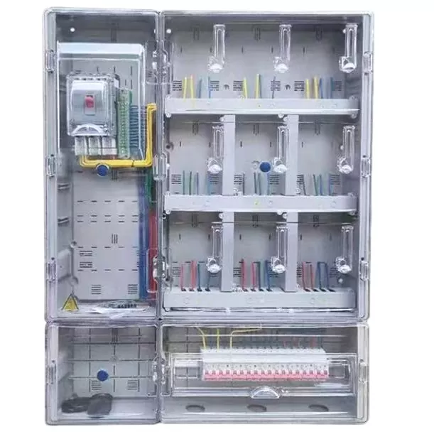
Bi-directional energy meter installation
Forward: PV power fed into the grid (electricity sold)
Reverse: Power drawn from the grid (electricity purchased)
Used for electricity billing settlement
4. Switching Control
Main circuit breaker (ACB/MCCB) serves as the master grid-connection switch
Manual/automatic disconnection for maintenance or fault handling
Provides electrical isolation between the PV system and the grid
5. Lightning Protection
Built-in AC Surge Protection Device (SPD)
Protects inverters and grid equipment against surges and lightning strikes
6. Monitoring and Communication (Smart Features)
Real-time monitoring of voltage, current, power, and energy
Supports RS485 / Ethernet communication
Enables remote monitoring and fault alarms